



Parallel low voltage batteries share current unevenly when one branch presents less electrical resistance or reports a different operating limit than the others. The battery on that branch works harder, reaches its protection threshold sooner, and can make the whole bank appear smaller than its calculated capacity. The remedy is not simply adding another module. You need symmetrical conductors, a suitable busbar layout, matched state of charge, reliable BMS communication, and a controlled commissioning test.
The issue often hides during light operation because every branch seems healthy. It becomes visible during a long discharge, inverter start, or high charging period, when small voltage drops produce a measurable difference in branch current. A useful inspection therefore compares each module at the same instant rather than reading only the total current at the inverter.
Key Takeaways
- Use a common busbar or an electrically symmetrical connection so each battery sees a similar cable path.
- Commission modules at a similar state of charge and verify that the inverter has the correct battery communication profile.
- Measure branch current, terminal voltage, and connection temperature under load; total bank current alone can hide an overloaded module.
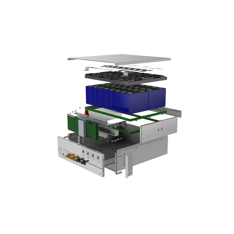
Current Follows Resistance Before It Follows the Nameplate
Parallel wiring holds every battery at the same bus voltage, but it does not force equal current through every branch. Each branch includes the battery’s internal resistance, fuse, connector, cable, lug, switch, and busbar contact. A branch with lower total resistance supplies more current at the same voltage difference. That is why identical model numbers do not guarantee identical loading after installation.
If one 100 A branch has 5 milliohms of total path resistance, it loses 0.5 V. A 7 milliohm branch loses 0.7 V at the same current, so current shifts toward the lower-resistance path. This is an electrical example, not a product tolerance; measure every path and minimize avoidable differences.
Four Sources of Imbalance That Appear in Real Installations
Uneven current rarely has one dramatic cause. More often, several small asymmetries add together. The following checks separate a wiring issue from a battery setting or condition issue.
Cable Length and Connection Topology
A daisy chain connection gives the nearest battery the shortest route to the inverter and the last battery the longest. Equal cable gauges do not correct unequal route length. Run equal-length positive and negative conductors from each module to common busbars, or use a diagonal connection only where the manufacturer approves that arrangement and the bank is small enough for it to remain symmetrical.
Contact Resistance at Lugs and Protection Devices
A loose lug, contaminated contact, poor crimp, or different fuse holder adds resistance that may be invisible at rest. Check torque against the component instruction, then compare voltage drop from each battery terminal to the common bus under load. Thermal checks help, but temperature cannot replace electrical measurement.
State of Charge and Module History
Connecting one fully charged module beside a partly charged module can trigger equalization current before the inverter starts. Modules with different age, cycle history, temperature, or firmware may also reach charge and discharge limits at different times. Match the module type, bring units to the state of charge specified for commissioning, and never assume a new replacement can be dropped into an operating bank without review.
BMS and Inverter Coordination
Current can also diverge when the inverter reads the wrong master battery, the communication chain is incomplete, or charge limits do not update correctly. Confirm CAN or RS485 wiring, termination, device addresses, master and slave order, and the inverter’s approved battery profile. If communication is unavailable, use conservative manual settings supplied for that battery rather than copying values from another chemistry or model.
What to Measure During Commissioning
Commissioning should prove that every branch contributes within an acceptable project limit. The manufacturer or system designer must define that limit because it depends on module count, instrumentation accuracy, operating current, and battery controls. The table below turns the check into observable evidence.
| Check | Method | What an Abnormal Result Suggests |
| Open-circuit voltage | Measure each isolated module before paralleling | State-of-charge mismatch or a module that needs investigation |
| Branch current | Use matched current clamps during the same charge or discharge interval | Unequal resistance, BMS limit, or module condition |
| Loaded voltage drop | Measure battery terminal to common bus on positive and negative paths | Cable, lug, fuse, switch, or busbar resistance |
| Connection temperature | Compare like-for-like joints after a controlled stable load | Localized resistance or insufficient connection integrity |
| BMS data | Review alarms, current limits, temperatures, and state of charge for every module | Communication, setting, temperature, or cell-balance issue |
A Product Example for a Modular Low Voltage Bank
The 5kWh Lithium Battery Low Voltage WV51100L provides 5.12 kWh nominal energy and 4.096 kWh usable energy per module at 51.2 V. Its listed recommended charge and discharge rate is 0.5C, with a recommended current of 50 A, and the product page allows up to 15 units in parallel. CAN, RS485, and RS232 interfaces are listed for system communication. These figures define the product boundary, but they do not remove the need for equal cable paths, coordinated protection, or module-level current checks.
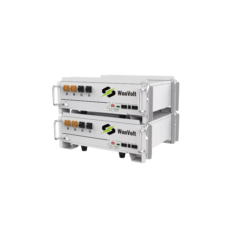
At the listed 4.096 kWh usable energy, ten modules provide 40.96 kWh before conversion losses and operating reserves. Capacity arithmetic, however, says nothing about whether one branch reaches its BMS limit early. Keep the design inside the product’s current, temperature, enclosure, and inverter compatibility conditions, and obtain approval for the exact parallel count and communication arrangement.
Two Field Errors That Shorten Useful Bank Capacity
The first error is taking one cable from the first module to the inverter and then bridging every additional module along the rack. The first branch repeatedly carries more current, while the last contributes less. The total capacity may look correct on paper, yet the first BMS can stop discharge before the remaining modules are fully used. A common bus with balanced branch conductors is the more controllable arrangement.
The second error is commissioning at low current only. A bank can look balanced while supplying a few amperes and separate sharply when current rises. Test a controlled charge and discharge step that is suitable for the installation, log every branch at the same timestamps, and stop if a connector heats abnormally or a module reports a protection event.
How to Correct an Existing Imbalance
Begin with evidence, not cable swapping. Save BMS logs, measure branch current, and record loaded voltage drops on both conductors. Isolate the bank according to the approved safety procedure before retorquing or changing hardware. Then correct one cause at a time and repeat the same load test so the result remains comparable.
- Replace unequal or undersized branch cables with matched conductors and routes.
- Move modules to a common busbar layout with individual branch protection.
- Correct BMS addresses, communication termination, master selection, and inverter profile.
- Equalize module state of charge through the approved procedure before reconnecting the bank.
- Investigate a module that remains consistently high or low after the external paths are balanced.
Depth of discharge also changes the energy available from the bank. The 80% depth-of-discharge discussion is a useful companion when setting an operating reserve, but current sharing still has to be confirmed at module level.
Specify the Bank as an Electrical System
A parallel battery purchase should define more than module count. Include the busbar arrangement, cable length and cross-section, branch protection, inverter model, communication protocol, parallel addressing, commissioning current, and acceptance method. WonVolt lists low voltage batteries and complete energy solutions, while its engineering support can review the equipment combination before installation.
For a new or corrective installation, send the single-line diagram, expected continuous and surge load, module count, cable schedule, ambient conditions, and inverter model through the technical contact channel. That information is far more useful than asking only whether batteries can be connected in parallel.
FAQ
Do parallel batteries have to use exactly the same cable length?
The objective is similar electrical resistance on every branch. Equal conductor material, cross-section, length, termination quality, and protection hardware make that result easier to achieve. Follow the battery and system designer’s approved layout.
Why does one battery reach empty before the others?
It may be supplying more current because its branch resistance is lower, or its BMS may calculate state of charge differently. Compare simultaneous branch current, loaded voltage drop, temperatures, alarms, and configuration.
Can batteries with different capacities be connected in parallel?
Do not assume they can. Different capacity, chemistry, voltage window, firmware, age, and BMS limits can create uncontrolled current sharing. Use only combinations approved for the exact product and inverter.
TDK
T: Why Parallel Low Voltage Batteries Share Current Unevenly and How to Fix It
D: Diagnose uneven current sharing in parallel low voltage batteries with cable, busbar, BMS, voltage drop, and commissioning checks.
K: parallel battery current sharing, low voltage battery bank, battery busbar wiring