



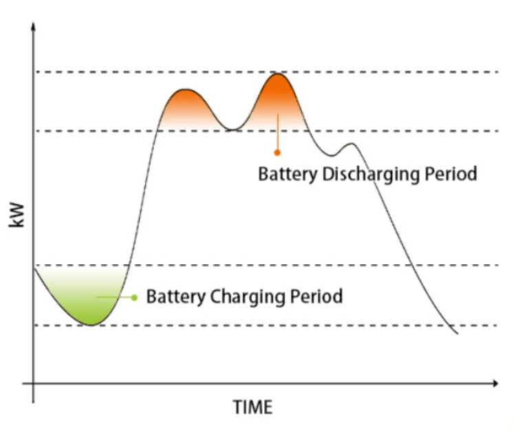
Look at the PCS during a busy operating period. The battery can be ready to discharge, but the converter may already be using part of its capacity to support voltage or meet a power factor target. Less kW is then available for peak shaving, even though the battery still has energy in reserve.
In assessing the interaction between the storage and the control strategy it is important to remember that the control strategy is part of the storage design. A useful assessment of the battery, PCS, EMS, meter, transformer etc. considers all of these in the context of the load profile and grid connection.
Wichtigste Erkenntnisse
- Reactive power helps to support AC voltage and power factor. Note that this does not add any stored kWh.
- The PCS apparently available power can be shared between active and reactive power.
- A meter installed at the PCS will display favorable values while the main supply point is still loaded with reactive power from motors and/or transformers.
- Prioritize between peak shaving, emergency reserve, self consumption of solar power and voltage support.
- For the selection decision active and reactive power curves of a battery are of equal relevance as the capacity of a battery.
What Reactive Power Means in C&I Battery Storage
An induction motor is made of a shaft, which is driven by the motor, and a magnetic field, which is generated by the motor. Similarly, for transformers and compressors, there is a relationship with the reactive current. This current does not produce any mechanical work, as it is with active power, but it still uses up space in the cables, in the transformers, and in the PCS.
The PCS Capacity Tradeoff
The relationship between these three quantities is given by the equation S² = P² + Q², where S is the apparent power in kVA, P the active power in kW and Q the reactive power in kVAr. When the apparent power S of the converter has reached its limits, an increase of Q only leaves less room for P while the charge of the battery does not reveal this limitation.
Short demand peaks on a production line: The battery is to be discharged while at the same time the grid connection requires reactive power. Both demands are limited by the kVA of the PCS and have to be reduced by the EMS. While on one site it might be more important to stabilize the voltage while on the other site demand reduction might be more important. Request the P-Q curve first to decide on appropriate battery size.
Power Factor at the Right Point
The power factor is the relation between the active power and the apparent power and it has to be as high as possible, because this results in as low as possible current for the same amount of active power in kW. Thus also current-related losses are reduced and a grid condition is fulfilled. Also the placement of the measuring device is important for the target value.
Even if the PCS value is within specifications and the downstream running motors are consuming reactive current, the main incomer may not reach its target value. Choose a measurement point and specify this in the operational specification, e.g. at the PCS terminals, on the low-voltage side, on the transformer side or even at the point of common coupling. Each of these locations offers a different view of the system.
How Reactive Power Control Changes System Performance
This allows for a more stable connection to site and better control of current. However, it limits the amount of active battery power that can be used in the design.
Effect on Peak Shaving
Active power is needed for peak shaving and energy arbitrage. While the PCS might reduce the amount of battery charge or discharge when the combined P and Q of the facility approaches its apparent power limit while having a fixed priority for reactive support, this has high value for the facility if voltage support has high value for the grid. It has lower value if the main goal of the project is to reduce demand.
Express your priorities in the operating schedule. A reserve at another site might be protected while at the same time peak demand of a tariff is reduced and the remaining reserve is used for reactive power support. Other sites might need to keep a strict band of voltage while producing less kW. Please state available kW at the required kVAr, how long the output is supposed to last, how fast it can be ramped up and down, and how it recovers.
Effect on Voltage and Stability
Reactive current can affect voltage on a weak feeder, long cable runs and heavily loaded industrial distribution buses. It can assist in starting large motors as well as compensate for rapid changes in output from renewable sources. However a fast loop can become unstable if there are significant delays in measurement, inverter response and associated EMS update intervals.
The site acceptance test needs to mimic normal operation. It should test for a reactive power step, start up a sample motor, fluctuate the renewable generation, and test grid connect/backup operations. It would be good to record voltage, current, real power, reactive power, power factor, setpoint, and alarms over time. A smooth response with limited overshoot is far more valuable than a fast response at light load.
Effect on Losses and Heat
Reactive power does not utilize stored energy like active discharge does, but still forces the power electronics to carry current. As a result, the losses in the converter as well as the heat are increased. Also, the fans, pumps, etc. for cooling of the system may consume even more auxiliary power. Thus, the overall efficiency of the system can decrease even when the battery’s DC energy flow appears to be normal.
Efficiency: Ask for battery round trip efficiency and total system efficiency as two different numbers. The test record should specify the following test conditions: Ambient temperature, DC voltage, AC voltage, Active power, Reactive power, and Duration. Two apparently similar efficiency numbers can represent very different operating points without specifying these conditions.
The PCS and EMS Need One Control Strategy
The PCS controls the AC output. The EMS tells the PCS what action to take with the AC output. The site meter then shows the result of the action. Reversed current transformers, incorrect phase order and sign errors are all simple matters but can cause enormous problems at first commissioning and frequently cause the system to correct the wrong problem.
Consider the PCS100-1000 Bidirectional Battery Inverter
WonVolt’ S 100 kW - 1000 kW Batterie-Wechselrichter, bidirektional, PCS100-1000 is a relevant product family for projects requiring bidirectional energy conversion across a 100 to 1,000 kW range. It provides a starting point for discussing industrial storage integration and converter sizing.
Before selecting a unit, ask for the current model-specific datasheet covering apparent power, permitted leading and lagging power factor, reactive power response, parallel operation, and temperature derating. Those details determine how much power factor correction can run alongside peak shaving. Do not treat the maximum kW rating as guaranteed simultaneous active and reactive output.
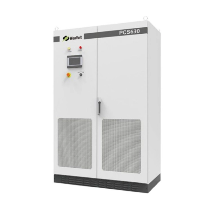
Compare devices using these values as a starting point and ask for project specific numbers, such as the P-Q curve, harmonic test conditions, over load capacity and active power at desired power factor. Also ask how kVAr is split when running in parallel. Cable impedance, firmware and meter placement can cause uneven output from seemingly identical devices.
EMS Priorities and Fallback States
Before tuning begins, agree on the control target, measurement point, priority order, deadband, ramp rate, and fallback state. The target could be fixed power factor, fixed kVAr, voltage support, or a schedule linked to production hours. The EMS should also record whether a limit came from the battery, PCS, transformer, grid connection, or site protection.
Die Industrie- und Gewerbelösung of WonVolt has three main functions: backup power, peak shaving and self-consumption. If all functions are required for a project, the operation sequence has to be fixed before start-up of the system. The reactive control by the EMS only makes sense if the EMS knows which function has to give up in case the PCS is reaching its limits.
A Practical Selection Checklist for Buyers
Reactive power is a test item in the RFQ, in the Factory Acceptance Test, and in the Site Acceptance Test. Simple charge/discharge tests on a system are not sufficient to guarantee that the system will also perform properly at the grid interface. All controls must have been tested interactively.
Electrical and Control Checks
- Define the point of measurement: PCS, bus, transformer or point of common coupling.
- P-Q curve and kW derating at the required kVAr for the various voltage limits as a function of state of charge and ambient temperature.
- Test step change of reactive power and of power factor. Record overshoot, settling time, rate of change of power and all alarms.
- Check current transformer direction, phase sequence, timer and sign before tuning.
- Request peak shaving, backup reserve, solar self-consumption, and reactive support together. Observe which function is curtailed.
- Harmonics on site at variable-speed driven and larger motor equipped areas, not simply test loaded equipment.
Thermal and Maintenance Checks
Check for trips on cooling, monitor cabinet temperature, verify adequate ventilation, check for blocked filters, and measure auxiliary power consumption during sustained reactive operation. Note: A short demo may not capture the gradual rise in temperature over a production shift. Ask if the sustained reactive output alters maintenance interval or derating.
Check battery model, test method, warranty boundaries and battery to PCS dispatch relationship when using this information for a forecast. The information in WonVolt’s product materials describes specific LiFePO4 C&I rack configurations with 80% DOD and >6,000 cycles @ 25°C.
How WonVolt Fits the Project Discussion
We are a clean energy solutions company specializing in industrial and commercial energy storage systems. Our company information includes pre-sale field investigation as well as post-sale engineering support for commissioning tests and technical training. Many factors related to a system’s reactive performance are influenced by site specific details including wiring, load behavior, metering, transformer limitations and grid settings.
Please refer to our company profile or complete the project parameters on the Kontaktseite. For a quotation please provide us with the single-line diagram of your facility, operational voltage, transformer size, interval load profile, largest motor, desired power factor, required kW and kVAr, reserve backup power, renewable energy contribution, ambient temperature, main & local protection settings and other local grid constraints if any. Also, it would be useful to see the proposed control sequence of alternative products before we provide you with a quote to establish whether or not the proposed product will improve your overall C&I system or simply add another operating mode to your existing PCS.
FAQ (häufig gestellte Fragen)
Q1: Does controlling reactive power add to the usable energy in the battery?
A: No, it just changes the AC current and voltage, it doesn’t add any kWh. PCS active power may even decrease when it is restricted by the system’s apparent power limit.
Q2: Can a C&I battery PCS provide reactive power while charging or discharging?
A: Often, if it supports four-quadrant operation and remains within its P-Q curve. Confirm simultaneous kW and kVAr limits at the required voltage and temperature.
Q3: Where should power factor be measured?
A: Power factor should be measured at the point of common coupling or at the point defined in the grid agreement. PCS measurement alone does not take into account the reactive power demand from site equipment such as motors and transformers.
Q4: Does reactive power control affect peak shaving performance?
A: Yes, since kW + kVAr has to be below PCS kVA limit, the EMS might cut back battery output at some point. That has to be set prior to commissioning, based on priorities and acceptable derating.
Q5: What information should accompany a C&I storage quotation request?
A: Provide the single-line diagram, transformer data, interval load profile, kW and kVAr targets, power factor requirement, renewable profile, backup reserve, temperature range, protection settings, and grid requirements. This supports site-specific PCS and control sizing.